3-ch Power Amplifier PCB Assembly instructions
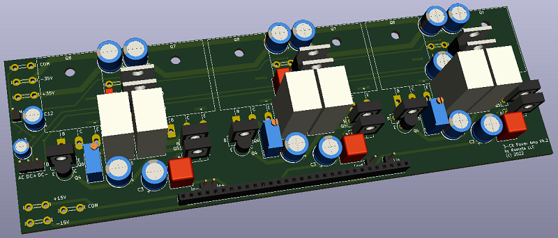
Figure 1. 3D PCB model
Assembly
Mount the amplifier to a suitable heatsink before connecting power. I used this 9.5" heatsink with my build. Make sure all power transistors' collectors are isolated from the heatsink. I recommend using kapton film with good thermal compound. For input signals you can use any suitable female headers or solder the crossover PCB directly. It is designed to work with only two 10-pin connectors on the sides to save money and time. Necessary pins are: 2 (+15V), 3 (-15V), 5 (Sig+), 8 (High), 10 (Mid), 26 (Low). All other pins are signal ground.
In order to prevent thermal runaway, transistors Q4 and Q6 need to be thermally connected. Put some thermal compound between them and pull them closely together with heat-shrink.
Testing (with dual lab power supply)
Connect power supply to the amplifier's "+35V", "-35V" and BOTH "COM" terminals. Set the current limit to 200-500 mA. Set RV1 to max value (measure resistance across pins 1 and 3 to be sure). Slowly start raising the supply voltage, keeping an eye on the current. With RV1 set to max, your supply current should stay low all the way to max voltage. And voltage across the rails should be roughly the same as supply voltage. If it starts to drop, or current starts to rapidly climb, stop the test and re-check everything. If everything goes well, connect a speaker and apply signal to the suitable input (Pins 8, 10 or 13, 22 or 26). If the amp works, disconnect everything and proceed to setting bias voltage.
Testing (without dual lab power supply)
Replace fuses with 20-30 Ohm 5W resistors. Connect power supply. Measure voltage on the supply rails. It shouldn't be less than ±20V. Measure DC voltage on the output. It shouldn't exceed 1V. If some of that isn't true, check the output transistors. If they are hot, disconnect the power supply and fix what's wrong. Connect a load and a signal and repeat the test. Proceed with bias voltage setting.
Setting bias voltage
There are different recommendations on what the appropriate bias should be, depending on who you listen to. My tests with my particular configuration didn't should significant difference in distortion in the class-B (class-AB) region. So my final recommendation would be 10-20 mV across the two 0.33 Ohm resistors.
Connect the amp to the power supply you are going to use in your project. Don't forget the signal ground. Connect multimeter between the output transistors' collectors (Pins 2) and set it to mV DC. Start lowering RV1 until the voltage settles on the desired level. Let the amp warm up and repeat the process. Keep doing it until you satisfied that the bias voltage stays on the desired level. You can seal the pot with glue, or replace it with equivalent resistor (if the pot's setting starts decreasing with age it will cause the quiescent current to increase and will eventually lead to overheating and failure).
Protection circuit
The PCB is provisioned with DC protection circuit. This circuit can be left out altogether by connecting pins 2 of Q12 and Q13 together with a thick jumper wire. But since the output of the amp is connected directly to the speaker, in the event of a catastrophic failure 35 VDC can develop on the output causing speaker failure. There are many different solutions to prevent that. The circuit utlilizes MOSFET relays Q12 and Q13 driven by SI8752. Capacitors C14, C15 and C16 set a separate DC detection threshold for each amplifier. The circuit has turn-on delay and loss of AC detection capabilities, which allow to disconnect the output while the transients are settling during turn-on and turn-off conditions. The loss of AC circuit requires 25VAC signal on the "AC" pin taken from the secondary of the transformer to operate (If you use my PCB, it has "Mute AC" terminal for this purpose). If you don't need loss of AC detection, use the jumper pads on the SMT side of the PCB (see figure 2) to bypass it.
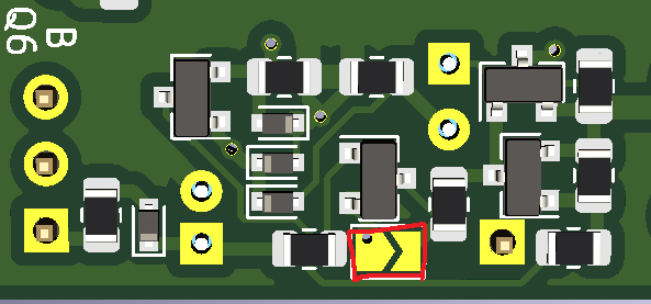
Figure 2. Muting bypass jumper
Pin "Mute" allows you to use internal DC detection with external relays (max output 100 mA at 35VDC). Or you can design your own circuit and just use "DC+" and "DC-" for DC detection signal (output impedance 100 kOhm).
Other terminals
Terminals "+15V", "-15V", "COM" proivide power to the pre-amp PCB via pins 1, 2, 3. Terminals "In+" (signal+), "In-" (signal-), "Lout" and "Lin" (allow summing left and right low channels for sub-woofer, described in more detail in the pre-amp assembly manual) are optional in case you want to connect wires to the amp PCB instead of pre-amp PCB.