Studio monitors. Part 2
Beginning here.
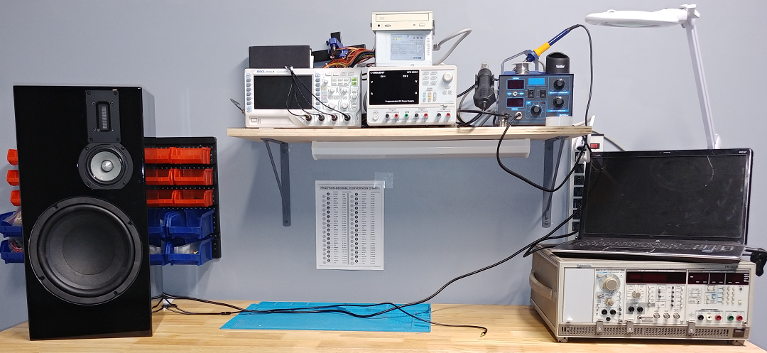
When it comes to building enclosures for your speakers, you have two choices: use hand tools or a CNC-router. It all comes down to how proficient you are in woodworking, what tools you have at your disposal, how much time you want to spend on it. I decided to take the CNC approach for my project, so I started with a 3D model of the design.
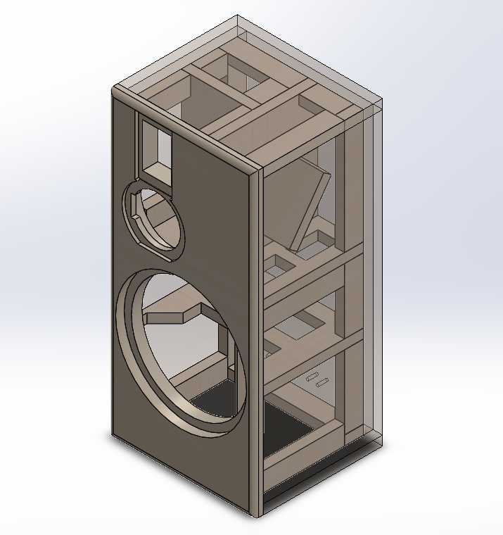
Figure 7. 3D-model of the right cabinet
All parts are designed to be cut out of a single 3/4" MDF (or HDF) board. The baffle will be composed of two panels glued together. The enclosure is heavily braced to increase the stiffness of the panels and to raise the resonant frequencies (the higher the resonance, the less acoustic power it has). The enclosure has two separate volumes for woofer and mid-range. The ribbon tweeter doesn't require a separate enclosed volume. The size of the baffle pretty much depends on the choice of the speakers, since we are staying in the "bookshelf" category for this particular project. The width will be just enough to fit in the woofer, and the height - to fit in the mid-range and the tweeter on top, and the amplifier with all the terminals in the bottom. By adjusting the depth we can regulate the volume to push the response of the woofer as low as possible (in our case it will be 15 liters).
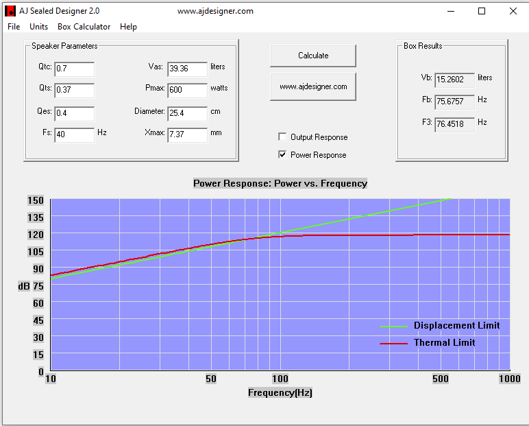
Figure 8. Woofer calculation
The mid/tweeter compartment is offset to the inside and is as close to the woofer as possible. As an added measure to reduce the standing waves the internal dimensions are chosen using the 'golden ratio' (with irrational multiplier to make sure the panels are not harmonically related). All parts are glued and screwed together and reinforced with epoxy to ensure complete air-tightness. It is also a good idea to epoxy all terminals and secure all the wires. Finally it will be tightly packed with fibreglass for additional dampening.
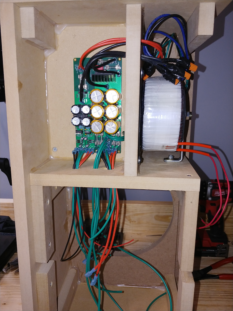
Figure 9. Assembly process
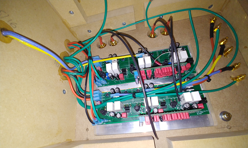
Figure 10. Assembly process
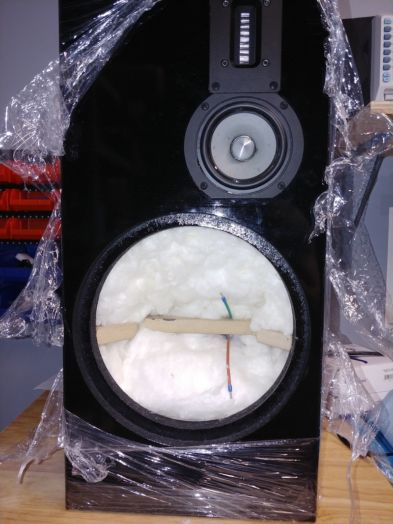
Figure 11. Assembly process
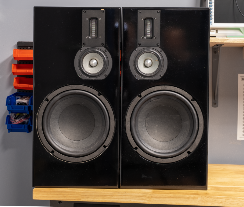
Figure 12. Assembly process
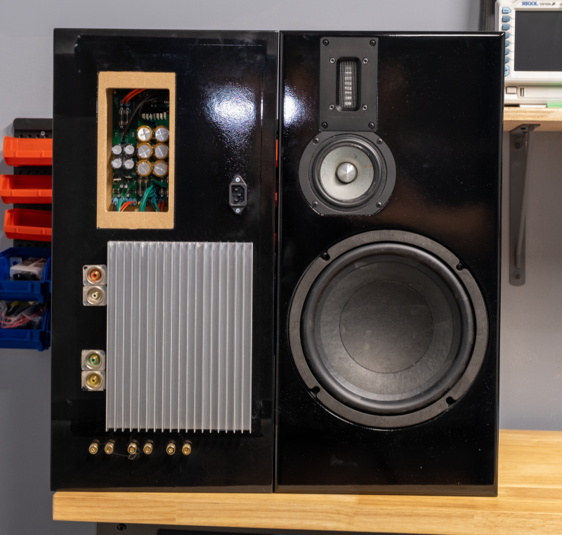
Figure 13. Assembly process
The cabinet turned out to be very heavy with the powered side weighing about 60 lb. The listening test was extremely satisfactory. The sound is clear, shows excellent balance between drivers with no panel resonance. When I get a chance I will take it to a sound lab to do proper measurements , which will help determine the crossover frequency for the future sub-woofer project.
Recommended reading:
- Loudspeaker Design Cookbook 7th edition (2020); Audio Amateur Pubns; ISBN 1882580478
- Loudspeaker Enclosure Design Guidelines
- Issues in loudspeaker design
Instructions and BOMs:
Attachments:
Power amp PCB Gerber (186.7 kB)
Xover PCB Gerber (94.2 kB)
Power supply PCB Gerber (170 kB)
Project files (13.4 MB)
Kicad libraries (4.9 MB)
Log in to leave comments