4-ch preamplifier PCB Assembly instructions
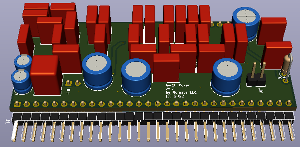
Figure 1. 3D PCB model
Output levels adjustement
The PCB comes with the ouput levels set for my project with -2dB High, +5dB Mid and +2dB Low to accomodate sensitivities of my tweeter, middle range and woofer drivers. If you want to change levels for your own project, you can use the output buffer values calculator and replace the resistors in thye voltage divider to provide required gain.
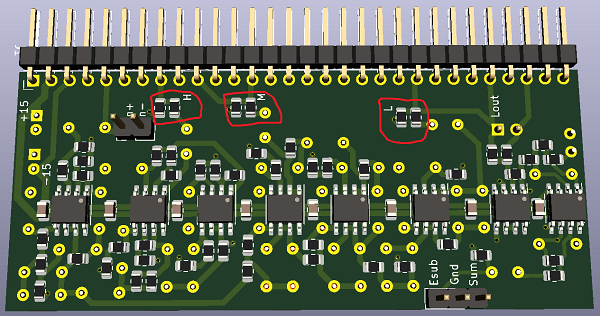
Figure 2. Output voltage dividers
Tweeter delay
The PCB provides about 40 usec tweeter delay with two cascaded 1st-order all-pass filters. If you want to eliminate this delay, remove 3 resistors according to Figure 3, and jump the joined pads to output capacitor.
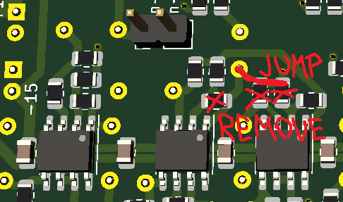
Figure 3. Bypassing time delay
Mid to low crossover frequency
The PCB is set for 668 Hz crossover frequency. If you want to change that use the calculator to find required resistor value (with 33 nF capacitors) and replace all 5.1 kOhm resistors on the PCB.
Subwoofer
PCB has two sub-woofer outputs. First is a simple sum of left and right channel low outputs with 180° phase shift. To set it up, choose which channel's outputs you are going to use, then connect "Lin" terminal on that PCB with "Lout" terminal on the other PCB. "ES" terminal provides experimentary output with -12dB/octave slope with 78Hz unity-gain. The PCB has provision for a resistor "G" to adjust the unity-gain. It has to be jumped if no resistor is used. I haven't tested the equilized output yet, so if you plan to use it, make sure you understand the principle behind this circuit. I will provide more detailed description, once I build my sub-woofer and run all the tests.