Studio monitors. Part 1
The goal of this project is to build affordable 3-way (extendable to 4-way) speaker system, that can challenge professional studio monitors when in comes to sound quality. There aren’t that many (if any) 3-way active speaker systems readily available to general public, mostly due to the costs of manufacturing process. So historically active speakers have been reserved for commercial use (sound recording studios), while home hi-fi systems were dominated by speakers with passive crossover networks. Even with recent progress in class-D amplifier's sound quality, they are still mostly used in cheaper lower-end bookshelf speakers and sound bars.
Initially I planned to build two speaker enclosures wired for tri-amping and a separate amplifier. But then decided to try and fit the amp inside the enclosure. It required using SMT components to build extremely small 6-channel amplifier with 4-way crossover network and speaker protection circuit. Let’s start with the amplifier topology.
The power supply is linear. A toroidal transformer with two center tapped secondary windings: 300VA 25V-0-25V and 50VA 15V-0-15V. While this configuration isn’t readily available, you can order it from multiple online stores. The secondaries are fused, just as both outputs. Only the low voltage supply requires stabilization. Both circuits are on the same PCB.
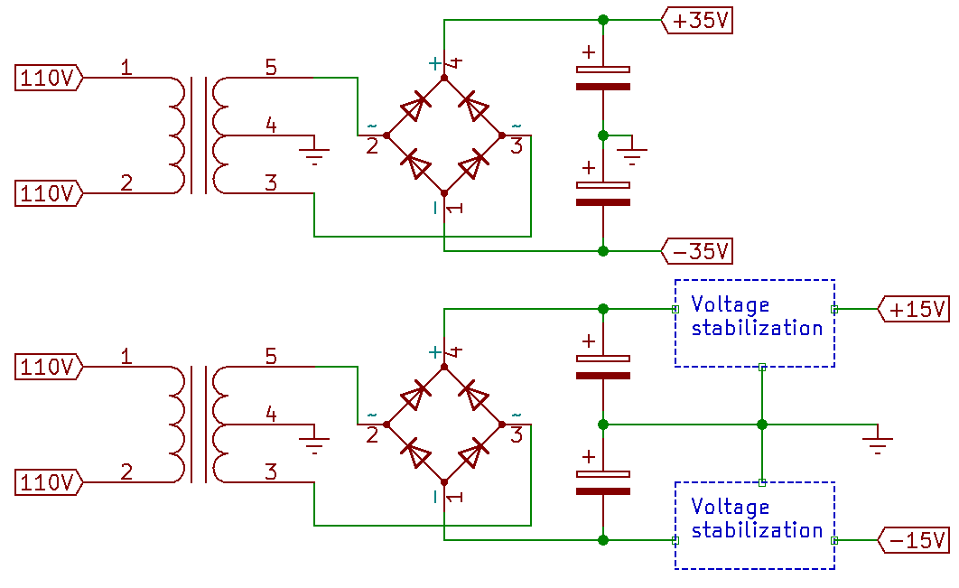
Figure 1. Power supply diagram
The crossover network is based on 4-th order Linkwitz–Riley topology. It provides 24db/octave roll-of with excellent phase-coherency, resulting in flat summed output at crossover frequency. A bandwidth definition filter removes all the subsonic signals and protects the loudspeakers. It consists of 3-rd order Butterworth highpass with 20Hz cutoff and 2-nd order Butterworth lowpass at 50kHz. The high frequency stage has 6dB gain to make signal less vulnerable to circuit noise. A cascaded 1st-order allpass filter provides a time delay to compensate for the difference in distance between tweeter’s and mid-range speaker’s acoustic centers and listener’s ear. Each output has a voltage divider, which allows to equalize the levels to each speaker’s sensitivity.
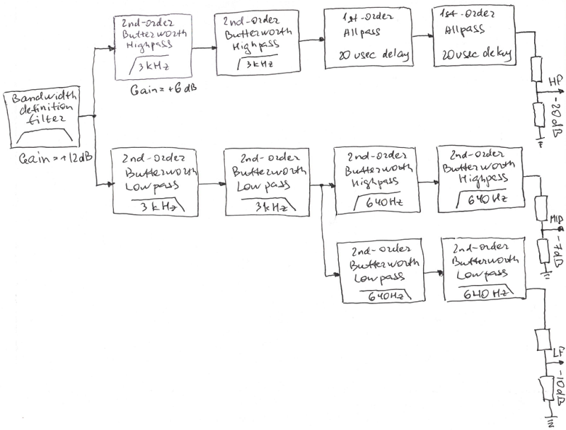
Figure 2. Crossover network configuration
In order to extend the bass all the way to the floor, the provision is made on the PCB for two bass signal outputs. One is just a sum of low inputs. The other one is passed through two intergrators to provide a 12db/octave slope for an equlised sub-woofer design.
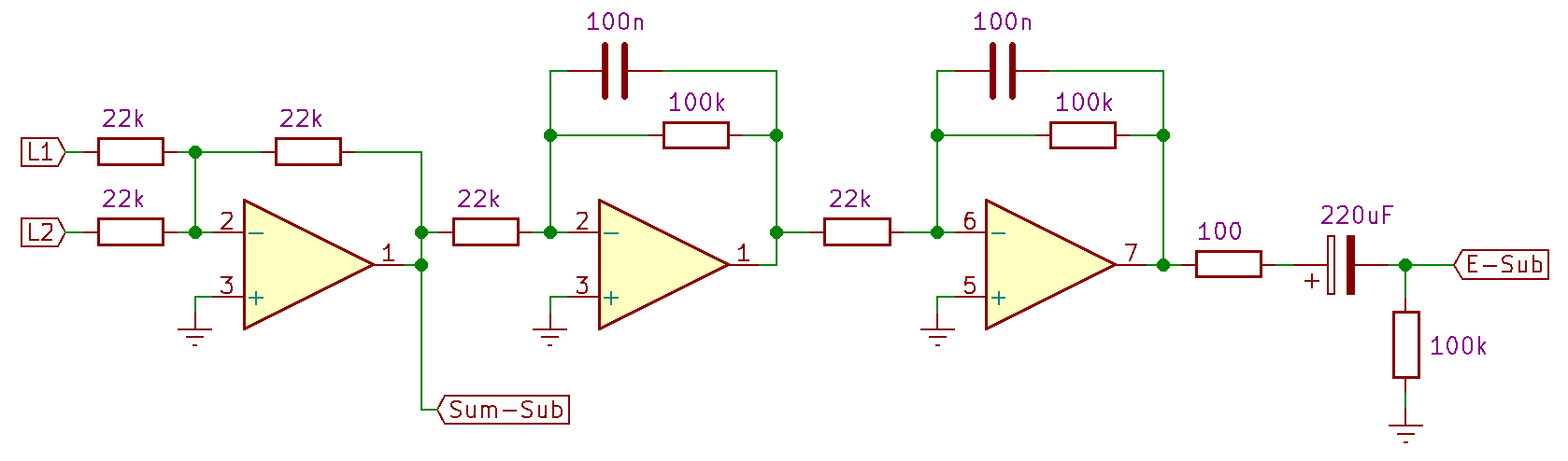
Figure 3. Sub-woofer output
The power amplifier is a conventional 3-stage class-AB. A long-tailed pair input stage converts differential voltage into output current signal. The second stage provides about 27dB of voltage gain. And the output is configured as a unity-gain complementary-feedback pair for better thermal stability and linearity. Since there will be no capacitor between the amplifier output and the loudspeaker, additional protection is required. Should DC develop on the output, it will destroy the loudspeakers (tweeter almost instantly). To prevent it the amplifier output stage is equipped with MOSFET relays that cut-off output in a matter of milliseconds (the actual delay depends on the lowest operating frequency and is individually configured for each loudspeaker).
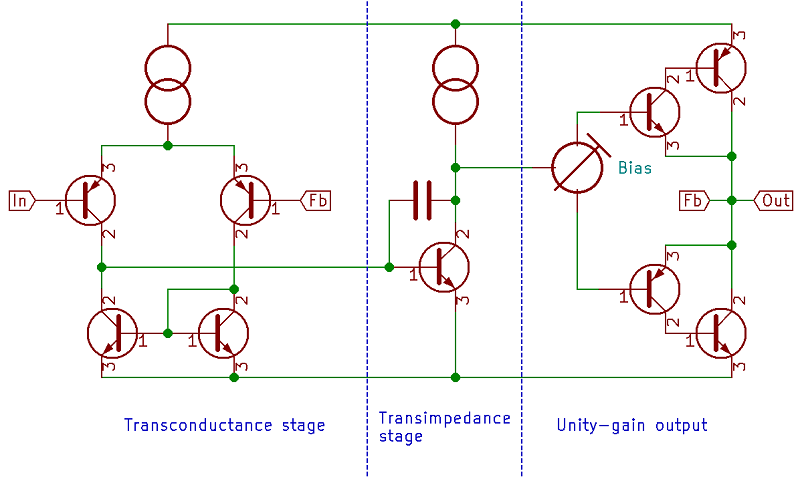
Figure 4. Power amplifier configuration
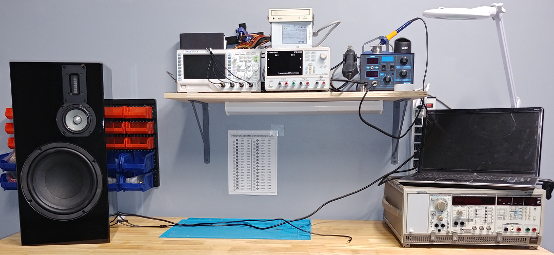
In order to fit 6 amplifiers and two 4-channel crossover networks into such a small form factor I had to go with SMT PCB design. I split the amp into 5 separate PCBs to keep routing simple and keep signal and power circuitry separate. The design proved to be exceptionally quite and stable, and is capable of producing 60W into 8ohm load from 35V power supply.
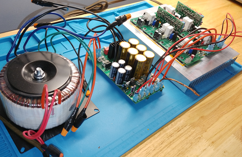
Figure 5. Finished amplifier
The final tests showed average THD+N = 0.02% at 60W. Low final bias current let's the amplifier run very cool. With my 0.4°C/W heatsink the idle temperature is about 40°C.
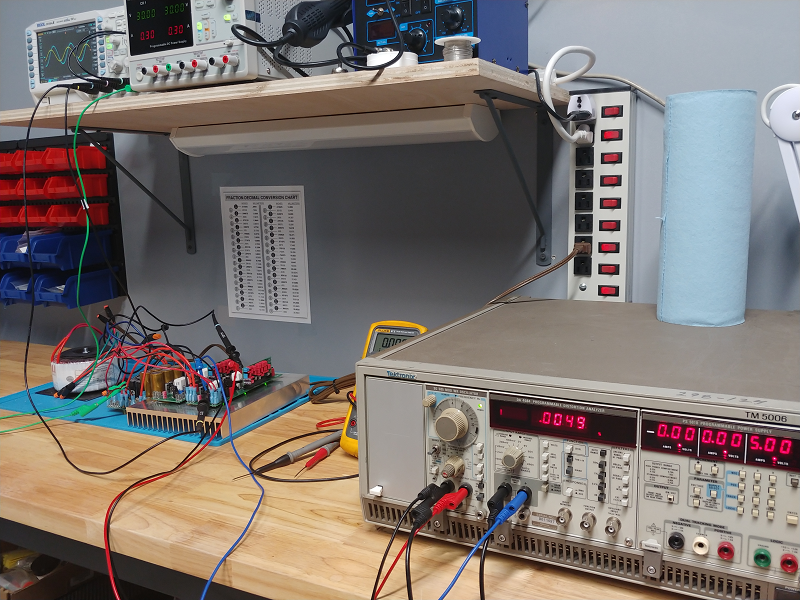
Figure 6. Amplifier testing
Speakers project continues in part 2.
Recommended reading:
- Small Signal Audio Design 3rd edition (2020); Routledge; ISBN 9780367468958
- The Design of Active Crossovers 2nd edition (2018); Routledge; ISBN 9781138733039
- Audio Power Amplifier Design 6th edition (2013); Routledge; ISBN 9780240526133
- Benefits of Bi-Amping (Not Quite Magic, But Close)
- Power Amplifier Design Guidelines
Log in to leave comments